It's the new version of the previous simple 5x7 LED dot-matrix circuit.
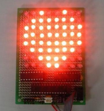
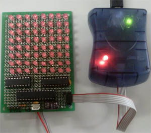
This a small LED dot-matix hardware with 8 coloumns by 8 rows of LEDs. It demonstrates how the LED message board works through the very simplified circuit which is comprised of 64 LEDs, a 8-bit data latch, a 8-bit sink driver, and a ATMega8 microprocessor. They were soldered on a prototyping pcb board.
After I explain how the hardware works altogether in order to get things done, I'll show you some sample codes for displaying any shape you want and how to integrate this LED board with the PC software.
I used AVR STUDIO 5 as the software development tool that can be freely, but you need to register, download from ATMEL company site. It has upgraded from the previous version 4 and included IDE from Microsoft Visual Studio and GNU C compiler.
1. LED part
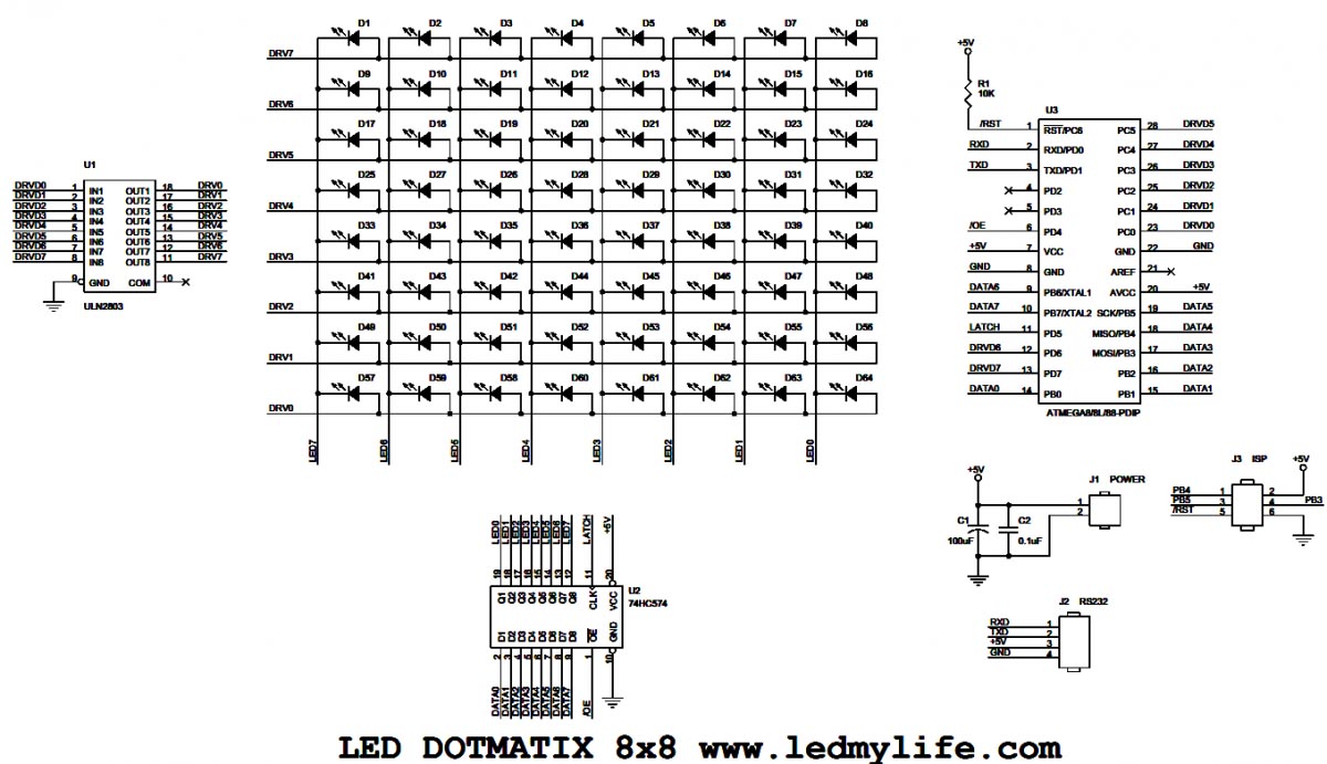
As you can see from the above, 64 LEDs are soldered by 8 rows and 8 columns. Each anode(+) and cathode(-) pins of a LED are connected to each columns and rows respectively which makes common lines for 8 data column lines and 8 driving row lines.
Data lines(LED0 ~ LED7) are directly connected to the output of 74HC574 which is used as a data latch during the driving time at a specific row line. Driving row lines(DRV0 ~ DRV7) are connected to UNL2803(or compatibles) which has 8-bit sink type TR array. Only one driving row line can be turned on when it is in the normal operation state. It is called 1/8 duty display. Following video demonstrates this behavior as I inserted some decaying delaying time in the code.
2. DATA LATCH part
74HC574 connect to the column lines of the LED matrix is 8-bit, 3-state D-type filp-flop IC which is triggered by an positive edge at CLK pin and displays a byte datum to each LED line synching with a driving signal of ULN2803. The inputs (D1 ~ D7) are connected to PORTB of ATMEGA8 which is used as the controller in this project and it also controls other control signals(/OE, CLK) as well. If /OE signal is in low voltage, the outputs(Q0 ~Q7) are appeared as the state( H or L) when the last latch was occurred at the positive edge trigger of CLK signal. But in the HIGH voltage of /OE signal, all the outputs of 74HC574 are in high-impedance states. I used this /OE signal to remove the ghost(?) signal that makes LED display blurred and unclear which appears when the change of driving signal is occurred. I'll explain later in the firmware article.
3. DRVING part
For the line driving of the LED matrix, a ULN2803 or TD62083 is used in this project. It is 8 channel sink driver and can drive up to 500mA per channel. In this application, the only one channel is turned on at a time synchronized with the output latch clock to the 74HC574. From the channel 0(DRV0) to 7(DRV7), it is sequentially switched on, then come back to the channel 0(DRV0) again and repeat this procedure recursively. The following picture help you to understand how it works.
4. MICROCONTROLLER part
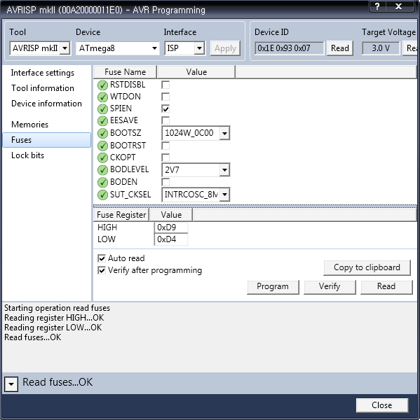
I used ATmega8L in PDIP package as the controller, but ATmega8 or ATmega88 can be possible as well. Atmega8 has 8KBytes sized promgram FLASH memory, 512Bytes EEPROM and 1024KBytes internal SRAM. Program FLASH can be easily programmed using AVRISP progammer tool and ATmega88 device has hardware debug function with DebugWire tools which is using the same pin with ISP.
I used 28pin PDIP package. The number of IO ports for PDIP package is more restricted than other packages, but it was sufficient for this application. For MCU clock, internal 8MHz clock was selected so the pins for the XTAL were also used as general IO ports. Here is the screen shot of fuse setting in AVR Sturio 5.
In this article, I introduced a simple 8x8 LED dot-matrix hardware and added some explanation about it. Next time I'll write about how it work with some example code using AVR Studio 5.